
You are using an out of date browser. It may not display this or other websites correctly.
You should upgrade or use an alternative browser.
You should upgrade or use an alternative browser.
How to power front seat inside a house?
- Thread starter nVIceman
- Start date
boosted1g
Sustaining Member
I would not suggest it. From what I can gather, it looks like output changes on that power-ground wire. So if you hook things up like you suggested then at best it will only work in 1 direction, at worst it wont work at all or even damage something.Thanks. Do you think it's worth it and safe trying to hook it up the way I describe to see if it would work?
Yes, the diagram is still using the seat buttons. You are disconnecting the lumbar module and takings its inputs (from the switch buttons) and instead connecting that to the relay inputs. Then you are connecting the relay outputs straight to the lumbar motors. Basically you are just bypassing the lumbar module.Does this relay board have a way to still use the buttons on the seat? I don't know how to read that diagram for how to make that work. Is it simple?
The inputs/outputs in the diagram match the pins of what you will find on a 4 channel relay like this one: https://www.amazon.com/HiLetgo-Channel-OPTO-Isolated-Support-Trigger/dp/B00LW2GM84
Logic:
A relay has 2 parts, the coil and the switch.
- The switch has 3 connections: Normally Open, Normally Closed and COM.
* COM: this is the output (in your case the lumbar motors)
* Normally Closed: this is what connects to COM when switch is in "off" position
* Normally Open: this is what connects to COM when switch is in "on" position
- The magnetic coil has a power and ground side, and is where you connect your input condition (in your case the seat button). When the coil is energized, it flips the switch above from NC to NO position
So what you are testing is connected to the coil, and what you wish to output (depending on condition) is connected to the Normally Closed and Normally Open pins.
IF condition = FALSE (coil not energized), COM = Normally Closed. IF condition = TRUE (coil energized), COM = Normally Open
How it works in your specific case.
The switch is your output connecting to the lumbar motors. Ground is connected to Normally Closed pins which by default goes to the COM pins which goes to the Lumbar motors. Thus when not pressing the seat switch button, pins 2 and 4 on both lumbar motors both receive ground, thus not driving the motor either direction
The coil is your input connected to the switches on the seat. The seat switches are a negative input (this means when pressed they send ground not 12v). Thus when the switch is pressed it creates a ground, it is wired to the IN on the relay and thus completes the ground, energizes the relay coil, and that flips the switch inside the relay from NC (ground) to NO (12v power) and thus sends power to the Lumbar Motor (COM pin).
So when you say press the lumbar down button - this signal travels to Pin 2 of S14 connector and goes to the IN on relay 2. This energizes the relay coil, flips the switch inside the relay, and now sends 12V power (from NO pin) over the COM wire to Pin 2 of the UP/Down Lumbar motor, thus giving power to Pin 2 and ground to Pin 4 and thus tells the motor to go in the DOWN direction.
Verbal Wiring Directions for Diagram:
The 4 channel board linked earlier has an NO, NC, and COM for each relay. It has an IN for each relay, and it has a shared DC+ (power), and DC- (ground).
- You will wire 12v power from battery up to each of the 4 NO relay pins
- You will wire ground to each of the 4 NC relay pins as well as to the DC- Pin
- You will need a fused 12v input (10A should be fine) to the DC+ Pin
- Cut the wires a few inches from the S12 and S13 connectors going to the lumbar motors
- Solder the respective COM wires from the relays to the S12 and S13 connectors for the motors.
- Unplug the S14 connector from the lumbar module.
- You can cut the needed wires (pin 1,2,8,9) from the connector or simply cut all of them.
- Solder the respective wires of the connector to the IN pins on the relay.
- These wires come from the seat switches, which are low side input (meaning when pressed they are a ground, not 12v power), thus all the jumpers on the relay should be changed from High to Low.
For ease of wiring all of the power and ground connections I would suggest getting some terminal blocks like this: https://www.amazon.com/Positions-Terminal-Pre-Insulated-Barrier-MILAPEAK/dp/B07CM1JQCR
FYI I had reversed the NC and NO on the original diagram. I have already changed and reposted the correct one. If you saved the original then delete it and redownload it.
BTW what are you using for power? A 450W computer power supply would actually work pretty well for this.
Last edited:
boosted1g
Sustaining Member
This diagram should provide a better visual to my explanation in the previous post (I only showed the UP/DOWN motor connections to make it easier to read)
You are completely bypassing the Lumbar module, and instead connecting its seat switch inputs to the relays.
You are then connecting the relay outputs directly to the Lumbar motors

You are completely bypassing the Lumbar module, and instead connecting its seat switch inputs to the relays.
You are then connecting the relay outputs directly to the Lumbar motors
______________________________
Thanks for all of that. I can only comprehend so much, but learning as I go. I will address some of the easier things. I am using a 12v cordless drill battery. I don't have any problem getting a power supply that I can wall plug, would prefer that anyways. I work on computers for my job, so very familiar with those power supplies, but not all that much with the electrical particulars for using outside of a computer. Is that the best PSU to use? It seems a bit over the top for this use case.
I only see you mention lumbar motors, up/down/inflate/deflate. There is another for the side bolsters, so it would be a 6-way adjustment that I would need to support.
I don't solder. Is there a solderless way of doing this. I use Tap Wire Connectors to snap into the cables and then plug in to battery that way.
I am going to try to remove back now. I might need to get some skinny long tools to assist though.
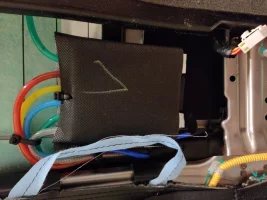
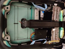
Hold the presses! I was able to get the back off and what I saw was nothing like I saw in pictures. There doesn't seem to be any motors, at least in the sense of regular motors like the others. One pic shows the whole back, one focus is on the air cell lumbar module, which seems to sucker blow air into or out of the six colored tubes above it. The green ones appear to go to each bolster on the sides and the other four would seem dedicated to the lumbar position.
The connector unplugged at the bottom right a bit is the s14 connector. The mystery connector on the bottom left that goes into blue sleeving and go somewhere down through additional blacks leaving near the bottom corner of the seat. From there, I do not know where it goes. There is a yellow and red cable inside of it and I do not see that anywhere, so unsure what that is and why it doesn't seem to be listed.
It does appear that taking this module out of the equation is impossible because it is blowing or sucking air through the tubes that are connected to it. It just seems to be a completely different implementation of the lumbar.
Attachments
boosted1g
Sustaining Member
A dedicated 12v 30+ amp power supply would be "better" just in the sense of less wires and more dedicated purpose.I work on computers for my job, so very familiar with those power supplies, but not all that much with the electrical particulars for using outside of a computer. Is that the best PSU to use? It seems a bit over the top for this use case.
However a PC power supply is at worst the same price (if you cant get your hands on a used one), but the PC power supply has teardown reviews on quality; vs the completely questionmark no-name 12v power supplies on amazon
Seriously, you should learn. This will help widen your skills as a PC/Hardware technican (that is what I started out as). Not to mention solder + heat shrink makes the most reliable connection vs any twist/crimp connectors.I don't solder. Is there a solderless way of doing this. I use Tap Wire Connectors to snap into the cables and then plug in to battery that way.
Looks like your assessment is correct. I do recall seeing a Kia lumbar module that was 3 pillows.It does appear that taking this module out of the equation is impossible because it is blowing or sucking air through the tubes that are connected to it. It just seems to be a completely different implementation of the lumbar.
How many wires are actually going to the S14 connector?
You can trace out the switch button wires.
- Set the multimeter to DC Volts and attach the red lead of the multimeter to the 12v drill battery (preferably using alligator clips because you will need both hands free).
-You will need the IMS module connected to the battery ground (this will provide ground to the seat buttons)
- Press one of the lumbar/bolster seat buttons and move the black multimeter lead from pin to pin in the S14 connector and see which one is 12v, then unpress that button, if it goes to 0V then that is the corresponding wire.
- Repeat until you have the seat buttons maped
Once done, tell me what wires/pins are left over
If anyone with KGIS or other source has a circuit diagram for this lumbar module that would be most helpful.
Last edited:
From interior to exterior to high performance - everything you need for your Stinger awaits you...
boosted1g
Sustaining Member
Yeah S14.I have S12 as Driver Lumbar Support Motor, but I don't think this seat has that. Did you mean S14? If you did, it's 11, as it appears on diagram, as pin 4 is empty just as it shows.
Well you can trace it out as stated above and see what that leaves for power/ground/other cables to the lumbar controller
I'll take a closer look and account for each cable I can. Now that you know there is just this module, does that change what you think about the 3 pins I thought needing connecting based on the IMS unit? There are also these other 2 on this other connector, but at this point they are unknown and I don't see why they would matter for powering it at least as clearly that goes through other connector.
boosted1g
Sustaining Member
It changes things in regards to using the relay module I suggested, because there is no motor, the controller is the inflator/deflator, so you either have to figure it out or it wont work.I'll take a closer look and account for each cable I can. Now that you know there is just this module, does that change what you think about the 3 pins I thought needing connecting based on the IMS unit? There are also these other 2 on this other connector, but at this point they are unknown and I don't see why they would matter for powering it at least as clearly that goes through other connector.
However you still dont want to just guess what the remaining wires are, and if it requries more than just 12v but some soft of logic/communication with the ICU (fuse box) in the car then I doubt it is something that would be easy for you to duplicate.
What you ultimately may need to do is test the remaining wires with it plugged into the car (or test on your seat if your seat is the same type).
______________________________
From S14 back down and through connector connecting it and reclining motor, all wires accounted for. I did notice that mystery connector on lumbar module is drawn but not labeled on the attached PDF. If you look at S14, it is to the right, the purplish pink connector that intersects the airbag wiring sleeve a bit, then attaches to something I cannot tell, not sure if that is grounding it or what, but it doesn't seem to lead anywhere.
Attachments
From interior to exterior to high performance - everything you need for your Stinger awaits you...
I just made an interesting discovery trying to trace out this mystery Pin 11 Lumbar Module ICU Junction Block (IPS5 - Body Load) red wire. I reliably got good contact on it, yet still nothing on the last remaining red wire unaccounted for in the FS11 Main Connector. I tried the other red wire that was the same thing but for the IMS module and continuity was made! I double checked, even checked the IMS module connector itself as well and sure enough, that same red wire in the main connector goes to both the lumbar module and IMS module for the same purpose, so must Y split off beneath the sleeving. Now, I have those 3 wires that it appeared I needed to power the lumbar module. One was already hooked up obviously since it has double duty.
I just figured out where that other red wire went. It's to the fan.
I just figured out where that other red wire went. It's to the fan.
I've accounted for all 16 pins/wires in the main FS11 connector. They go to IMS, lumbar aircell module, fan blower, seat warmer, and BODY-CAN for both IMS/Lumbar Aircell Module.
I would like to get the fan going, but it doesn't work with just power and ground, need to connect into the speed control wire, not sure what device to use for that. I'm thinking some kind of switch that can cycle through the speeds.
Seat Warmer would be nice in the winter, but not a priority, so unless simple enough to wire now, may defer.
Another update. I figured I'd give lumbar module a shot. I had some of what I needed hooked up already anyways since it had double duty, but it was no go. I couldn't use any of the air cells. The following link is actually the lumber module and air cells that I have for a better look at it all. Does anyone have an idea how much wattage the air cell module would use? I wonder if maybe it's more than what my battery is supplying that works for the regular motors.

I did discover that the body load pin for the IMS is not needed. The five motors work fine through the seat switches with that disconnected. That was the shared connection between the lumbar and the IMS.
2018 - 2021 KIA STINGER FRONT LEFT SEAT LUMBAR SUPPORT PAD SET W/PUMP 88340J5100 | eBay
Find many great new & used options and get the best deals for 2018 - 2021 KIA STINGER FRONT LEFT SEAT LUMBAR SUPPORT PAD SET W/PUMP 88340J5100 at the best online prices at eBay! Free shipping for many products!
www.ebay.com
I did discover that the body load pin for the IMS is not needed. The five motors work fine through the seat switches with that disconnected. That was the shared connection between the lumbar and the IMS.
boosted1g
Sustaining Member
Even a 2 ah battery can provide 10 amps or more for a short burst.
With that said, power drain is not linear. A battery at 90% will drain way more than 2x faster vs that same battery at 45% load.
Easy enough to see if it is the battery or not.
Fully charge the battery and test the voltage. It should read high 12 - low 13 volts.
Now hook it up and test the lumbar. If lumbar budges then the battery size is likely too small.
If the lumbar motor does nothing after a few seconds holding down the seat button then disconnect battery and recheck voltage.
If it is the same voltage then issue is something still not connected right with lumbar.
If the voltage has dropped then battery is too weak for needs of lumbar motor.
Hip hip hooray! It has been accomplished at last! I just needed a charge up the battery, then all the lumbar functionality worked. I'm excited to get all of this working and look forward to getting it installed. However, I still need to figure out exactly how I'm going to connect everything permanently.Even a 2 ah battery can provide 10 amps or more for a short burst.
With that said, power drain is not linear. A battery at 90% will drain way more than 2x faster vs that same battery at 45% load.
Easy enough to see if it is the battery or not.
Fully charge the battery and test the voltage. It should read high 12 - low 13 volts.
Now hook it up and test the lumbar. If lumbar budges then the battery size is likely too small.
If the lumbar motor does nothing after a few seconds holding down the seat button then disconnect battery and recheck voltage.
If it is the same voltage then issue is something still not connected right with lumbar.
If the voltage has dropped then battery is too weak for needs of lumbar motor.
Before I do all of that, I would like to get the fan blower motor working as well.
Thanks to everyone who helped me. I was starting to wonder if I was going to be able to accomplish all of this whether or not it was accomplishable.
______________________________
From interior to exterior to high performance - everything you need for your Stinger awaits you...
boosted1g
Sustaining Member
I was looking at the fan blower, It is 3 wire, obviously 1 is 12v, 1 is ground and one is fan speed.
Traditionally fan speed is done by using resistors to vary how much load can go to the motor.
You should be able to use something like this: https://www.amazon.com/Controller-Universal-Electronic-Stepless-Regulator/dp/B07T35JDTR
Of course you could always just supply 12v and have 1 speed.
For permanent I would hard-wire a PC power supply or a 12v power supply with 20+ amps output.
I would envision building some base for the chair out of wood, and then take a piece of sheet metal and cutout some holes for some toggle switches and the fan speed control.
I would have 1 toggle switch for the power supply (that would then provide power for lumbar and seat adjustment), 1 for the blower motor, and then the speed control knob.
You can extend the wires for the built-in switch for the Power Supply, just be careful while disassembling a power supply because even unplugged the caps and transformers WILL SHOCK YOU if you touch them.
For the fan blower, I did figure just supplying power and ground would make it run, but it didn't budge. I can charge up battery again and see if the reason it didn't work was the same as for the lumbar module.
I've had my cockpit built for awhile. Chairs sit on 80/20 aluminum. I'll post a picture later. Let me see if I can get this fan working first. Thanks.
I've had my cockpit built for awhile. Chairs sit on 80/20 aluminum. I'll post a picture later. Let me see if I can get this fan working first. Thanks.
boosted1g
Sustaining Member
There is a 3rd wire on the blower that has to be hooked up. Giving it straight 12v should make it run on highFor the fan blower, I did figure just supplying power and ground would make it run, but it didn't budge. I can charge up battery again and see if the reason it didn't work was the same as for the lumbar module.
I've had my cockpit built for awhile. Chairs sit on 80/20 aluminum. I'll post a picture later. Let me see if I can get this fan working first. Thanks.
I just tried it multiple times like that, still didn't budge, battery was near full charge, voltage is exactly showing over 13 volts on it.There is a 3rd wire on the blower that has to be hooked up. Giving it straight 12v should make it run on high
I just tried an old computer power supply that still worked well enough for testing or at least I figured it probably did. It did! Fan ran full blast, which is probably too much all the time, so I will need a switch. I'll revisit this later after work.
From interior to exterior to high performance - everything you need for your Stinger awaits you...