
You are using an out of date browser. It may not display this or other websites correctly.
You should upgrade or use an alternative browser.
You should upgrade or use an alternative browser.
How to power front seat inside a house?
- Thread starter nVIceman
- Start date
RogueIV
Stinger Enthusiast
- Joined
- Jul 29, 2020
- Messages
- 865
- Reaction score
- 581
- Points
- 98
I assume it does but I couldn't find a pinout for that one.Sounds good, thanks. So does the connector that goes into connector b feed back to the main seat connector that would plug into the car? I'm figuring I would just crimp into the cables just outside of where they plug into the IMs unit, I was just wondering if there would be nothing on the other end as obviously the seat is not plugged into a car.
Okay, I just wanted to make sure I was okay crimping into the wires here without needing to unplug the connector. I feel like it's the easiest way.I assume it does but I couldn't find a pinout for that one.
______________________________
Well, although it is awkward, tight, and angled, I thought I got some metal to metal contact on the spade connectors I tried since they seem to fit around the metal tips inside where Connector B plugs into, I wasn't able to adjust the seat. I suppose maybe the contact wasn't there, but I wiggled around, so I think it should have been there.
Trying to remove the IMS unit to access better to do this seems much more involved than the documentation lets on. I don't see how I get it out. It looks like I would need to remove that big plastic piece in which some screws are screwed in from the other side. I am not sure what road I want to go down next. I do have a multimeter, but I have never used, don't quite understand how it would work to test even after researching it.
Trying to remove the IMS unit to access better to do this seems much more involved than the documentation lets on. I don't see how I get it out. It looks like I would need to remove that big plastic piece in which some screws are screwed in from the other side. I am not sure what road I want to go down next. I do have a multimeter, but I have never used, don't quite understand how it would work to test even after researching it.
RogueIV
Stinger Enthusiast
- Joined
- Jul 29, 2020
- Messages
- 865
- Reaction score
- 581
- Points
- 98
How to Test Continuity with a Multimeter use this method to see if any of the wires in that main connector goto the module.
There's also the possibility that the module will refuse to operate without seeing the rest of the car. Not exactly sure since i haven't pulled a seat out of a stinger and fiddled with one.
There's also the possibility that the module will refuse to operate without seeing the rest of the car. Not exactly sure since i haven't pulled a seat out of a stinger and fiddled with one.
From interior to exterior to high performance - everything you need for your Stinger awaits you...
I was able to figure out the continuity. It turns out the two blacks go to one of the blacks on the main connector and The two reds go to the one red on the main connector. But I plugged everything up with the 12 volt battery I have and I know I had proper contact and I couldn't get any of the motors to function to move the seat.How to Test Continuity with a Multimeter use this method to see if any of the wires in that main connector goto the module.
There's also the possibility that the module will refuse to operate without seeing the rest of the car. Not exactly sure since i haven't pulled a seat out of a stinger and fiddled with one.
I even tried going into one motor directly and although I couldn't be sure if I had proper contact on that one, it didn't even move. Even if since it doesn't see the entire car it won't let the motors work, I should definitely be able to get a motor to work if I power it directly, correct?
RogueIV
Stinger Enthusiast
- Joined
- Jul 29, 2020
- Messages
- 865
- Reaction score
- 581
- Points
- 98
If the connections are right and the motors are normal 2wire brushed motors - yesI was able to figure out the continuity. It turns out the two blacks go to one of the blacks on the main connector and The two reds go to the one red on the main connector. But I plugged everything up with the 12 volt battery I have and I know I had proper contact and I couldn't get any of the motors to function to move the seat.
I even tried going into one motor directly and although I couldn't be sure if I had proper contact on that one, it didn't even move. Even if since it doesn't see the entire car it won't let the motors work, I should definitely be able to get a motor to work if I power it directly, correct?
Last edited:
RogueIV
Stinger Enthusiast
- Joined
- Jul 29, 2020
- Messages
- 865
- Reaction score
- 581
- Points
- 98
and yes this appears to use normal 2 wire DC brushed motorsIf the conntection are right and the motors are normal 2wire brushed motors - yes
Okay, I'll try to get a better connection so I know it's there. What are the other 2 cables for then? I noticed 4 cables in total on 2 of the motors.and yes this appears to use normal 2 wire DC brushed motors
______________________________
From interior to exterior to high performance - everything you need for your Stinger awaits you...
Thanks, I did. I just tried knowing that I had solid connectivity with the thigh extension motor and tried to move it both directions, didn't move at all, so I cannot even power motors directly. I don't get it.I highly suggest consulting the factory service manual, there's a bunch of diagrams in the seat motor section showing what connections move the motors on the motor connectors.

Thanks, that did the trick. I even found that from Connector A on the IMS unit (which I later saw in the diagram, but traced wires and figured out myself) that 5 of the 7 motors are in it (positive/negative), so I can power each of those motors either direction directly from that connector, so I played with the 5. Apparently, the lumbar and side bolster aren't part of memory, so they don't go there, so now I have to figure out where those motor wires are going. They have to come down to the bottom of the seat obviously. I've seen some maybes, but if I can find those, I think I can work with this.Thats weird and doesn't make much sense. You did unplug them from the harness first right? Otherwise power might be shorting through the controller
boosted1g
Sustaining Member
Not sure if there even is any access to the wiring side of the control knobs, but I would be checking power and continuity through the entire system. I would be checking to make sure there was voltage input and output from the controls.
Now what is odd is that you cant power the motors directly. Are you using a battery with enough amps for the job?
Now what is odd is that you cant power the motors directly. Are you using a battery with enough amps for the job?
You must not have read my last post. I am able to power motors directly, at least the 5 going through Connector A of IMS unit. I found motor power wires for reclining motor going through a joint connector it looks like. I didn't see any other wires that looked like power, but it would seem that some cables feed a Lumbar Air Control Unit that then sends signals to adjust lumbar, so not sure if I can adjust from seat controls if I managed to power that or not, but would definitely be more ideal to power that controller versus the up/down/in/out/deflate/inflate whatever options this seat has. Seems like up/down/inflate/deflate is what it has and that is better than simply in/out, but I can't quite figure out how to power that controller. It only shows one wire going into a Power Ground as it's called.Not sure if there even is any access to the wiring side of the control knobs, but I would be checking power and continuity through the entire system. I would be checking to make sure there was voltage input and output from the controls.
Now what is odd is that you cant power the motors directly. Are you using a battery with enough amps for the job?
There is another set of positive/negative on the main connector that I do not know where it goes. Supplying power, couldn't do anything with lumbar/bolsters, but not sure if seat controls have some separate wiring that bypasses IMS unit. It would seem so considering that the IMS connector shows no lumbar/bolsters switches.
______________________________
From interior to exterior to high performance - everything you need for your Stinger awaits you...
boosted1g
Sustaining Member
Yeah your last post had not shown when I wrote what I did.You must not have read my last post. I am able to power motors directly, at least the 5 going through Connector A of IMS unit. I found motor power wires for reclining motor going through a joint connector it looks like. I didn't see any other wires that looked like power, but it would seem that some cables feed a Lumbar Air Control Unit that then sends signals to adjust lumbar, so not sure if I can adjust from seat controls if I managed to power that or not, but would definitely be more ideal to power that controller versus the up/down/in/out/deflate/inflate whatever options this seat has. Seems like up/down/inflate/deflate is what it has and that is better than simply in/out, but I can't quite figure out how to power that controller. It only shows one wire going into a Power Ground as it's called.
There is another set of positive/negative on the main connector that I do not know where it goes. Supplying power, couldn't do anything with lumbar/bolsters, but not sure if seat controls have some separate wiring that bypasses IMS unit. It would seem so considering that the IMS connector shows no lumbar/bolsters switches.
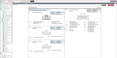
I am looking at the diagram provided on page 2 of the thread.
The 2 power connectors on the B connector do not power the IMS at all, they are simply the output power of the relays to the motors, so only connecting power to B1/B3 will not allow the switches to work.
B+ (pin C28) is what energizes the coil of the relays to allow it to work. There is also IGN (pin C14) that is also required to make the IMS turn on.
There is also a Ground on pin C20. This provides the needed ground input to the switch when pushed.
>> So to make this work you also need a (likely fused low-amp) 12V input on C28 and C14, and ground on C20
Logic wise:
The switches on the seat is an electric OPEN when not pushed, when pushed the corresponding switch connects to ground on pin C20. This ground then goes through IMS to the relays, grounding the coil and thus energizing it(power coming from B+ on C28), the now energized relay flips the switch inside thus allowing power from B1/B3 to flow to the proper motor.
With all of this said, has anyone verified the IMS will even work without the CANBUS connection? Even with everything else properly connected, there is a chance it could reject to send data from switch to motor without an established CANBUS connection.
Worst case scenario you can always connect your own relay board to the switches on connector C to send power to the motors on connector A, thus bypassing the IMS completely. You can get 8 or 16 channel relay boards on amazon for fairly cheap.
Last edited:
Thanks. I was having some trouble following some of what you said, but I think I got the gist of it. Regarding the last paragraph. That sounds like if that worked, it would allow me to use a seat buttons to adjust the five motors connected through the IMS. There are actually three other motors, two for lumbar, one for side bolster. It would still seem that I would need to find a way to connect those, which at this point I'm not quite sure how I power those.Yeah your last post had not shown when I wrote what I did.
I am looking at the diagram provided on page 2 of the thread.
The 2 power connectors on the B connector do not power the IMS at all, they are simply the output power of the relays to the motors, so only connecting power to B1/B3 will not allow the switches to work.
B+ (pin C28) is what energizes the coil of the relays to allow it to work. There is also IGN (pin C14) that is also required to make the IMS turn on.
There is also a Ground on pin C20. This provides the needed ground input to the switch when pushed.
>> So to make this work you also need a (likely fused low-amp) 12V input on C28 and C14, and ground on C20
Logic wise:
The switches on the seat is an electric OPEN when not pushed, when pushed the corresponding switch connects to ground on pin C20. This ground then goes through IMS to the relays, grounding the coil and thus energizing it(power coming from B+ on C28), the now energized relay flips the switch inside thus allowing power from B1/B3 to flow to the proper motor.
With all of this said, has anyone verified the IMS will even work without the CANBUS connection? Even with everything else properly connected, there is a chance it could reject to send data from switch to motor without an established CANBUS connection.
Worst case scenario you can always connect your own relay board to the switches on connector C to send power to the motors on connector A, thus bypassing the IMS completely. You can get 8 or 16 channel relay boards on amazon for fairly cheap.
They seem like they go through this joint connector at the bottom left when you're looking at the bottom if you lay the seat backwards. The power to the reclining motor goes through there.
Although, if I was able to connect the IMS like you were first talking about, that would obviously be great, so hopefully that would work.
boosted1g
Sustaining Member
Those other 3 motors where not in the IMS diagram. Have you even found any additional plugs for them? Get me the wiring diagram for them and I can take a look.Thanks. I was having some trouble following some of what you said, but I think I got the gist of it. Regarding the last paragraph. That sounds like if that worked, it would allow me to use a seat buttons to adjust the five motors connected through the IMS. There are actually three other motors, two for lumbar, one for side bolster. It would still seem that I would need to find a way to connect those, which at this point I'm not quite sure how I power those.
They seem like they go through this joint connector at the bottom left when you're looking at the bottom if you lay the seat backwards. The power to the reclining motor goes through there.
Although, if I was able to connect the IMS like you were first talking about, that would obviously be great, so hopefully that would work.
Last edited:
Starting here, this shows S14, which would be what I have since I have aircell lumbar. It goes along, meets up with reclining motor, then they both go to joint connector. Then, we have diagram showing lumbar control unit for the aircell type, then the IMS unit on the other one. These are the only ones showing anything lumbar that I've found or someone has sent me.

Attachments

boosted1g
Sustaining Member
Do you have a wiring circuit diagram for the actual LCM? Similar to the schematic diagram for the IMS: http://www.kstinger.com/integrated_memory_seat_ims_unit-786.html
It is likely just a case of providing power and ground to the right pins for it as well.
It is likely just a case of providing power and ground to the right pins for it as well.
From interior to exterior to high performance - everything you need for your Stinger awaits you...