
You are using an out of date browser. It may not display this or other websites correctly.
You should upgrade or use an alternative browser.
You should upgrade or use an alternative browser.
How to power front seat inside a house?
- Thread starter nVIceman
- Start date
boosted1g
Sustaining Member
Ok good on the blower coming on.I just tried an old computer power supply that still worked well enough for testing or at least I figured it probably did. It did! Fan ran full blast, which is probably too much all the time, so I will need a switch. I'll revisit this later after work.
Just get yourself a speed control knob like the one I linked earlier and should be good to go.
Looks like the seat takes a 30 amp fuse, so yeah the battery was probably just not enough
I know you mentioned at least 20 amps. If seat takes 30, should I actually get a 30? What a 20 can do far exceeds any wattage I would ever simultaneously pull, at least I'm pretty sure. I figured I'd get away with less than 20 really, but I didn't want to cut any corners if a certain amperage was needed or recommended.
______________________________
boosted1g
Sustaining Member
I said the 20 amp before seeing the fuse rating, so if buying something specific for it then go for 30.I know you mentioned at least 20 amps. If seat takes 30, should I actually get a 30? What a 20 can do far exceeds any wattage I would ever simultaneously pull, at least I'm pretty sure. I figured I'd get away with less than 20 really, but I didn't want to cut any corners if a certain amperage was needed or recommended.
20 should be totally fine as long as not running the blower and making 2 simultaneous adjustments, but yea better to use 30 since that is what KIA engineers used.
Mean Well makes some good power supplies. Much neater and better fitting profile for this one. 29 amps seems close enough. They aim for round wattage numbers.I said the 20 amp before seeing the fuse rating, so if buying something specific for it then go for 30.
20 should be totally fine as long as not running the blower and making 2 simultaneous adjustments, but yea better to use 30 since that is what KIA engineers used.
MEAN WELL LRS-350-12 Switching Power Supply 350W 12V 29A Constant Current https://a.co/d/4oLVxoB
Looking at these DC motor speed controllers, as far as I can tell, there doesn't seem room to plug-in to the speed controller pin. Would I just be connecting that to the Power + connection along with the actual power pin?
From interior to exterior to high performance - everything you need for your Stinger awaits you...
boosted1g
Sustaining Member
Not sure if you are looking at the same controller as the one I linked, but the one I linked just has 3 wires coming out of it.Looking at these DC motor speed controllers, as far as I can tell, there doesn't seem room to plug-in to the speed controller pin. Would I just be connecting that to the Power + connection along with the actual power pin?
You will need to bypass the blower controller, so just cut the wires at the blower motor pigtail and wire directly to it.
Based on the blower pigtail diagram you would connect pin 2 of blower and "power -" of the speed controller to ground, connect pin 4 of blower and "power +" of speed controller to 12v, and connect "motor -" to pin 3 of blower motor
The part about pin 3 speed controller of blower to motor -. I thought motor - would be pin 2 of blower and that the ground wires don't touch from speed controller to blower. They just passthrough the ground back to power supply. Motor - blue wire sounded like it would go to blower ground.
Reading comments, someone who used it described it as such.
"Wire up instructions are shown in the third picture in the selling description. Blue wire goes to the motors negative wire. Red wire goes to battery positive wire and motor positive wire, all three twisted together. Black wire goes to battery negative wire . I used it on a small RV vent fan motor. Works very well."
boosted1g
Sustaining Member
Those instructions are for a 2 wire fan, the blower in the car is a 3 wire.The part about pin 3 speed controller of blower to motor -. I thought motor - would be pin 2 of blower and that the ground wires don't touch from speed controller to blower. They just passthrough the ground back to power supply. Motor - blue wire sounded like it would go to blower ground.
Reading comments, someone who used it described it as such.
"Wire up instructions are shown in the third picture in the selling description. Blue wire goes to the motors negative wire. Red wire goes to battery positive wire and motor positive wire, all three twisted together. Black wire goes to battery negative wire . I used it on a small RV vent fan motor. Works very well."
Thinking more on it, Kia could have wired that fan a few different ways for using the 3rd wire.
Could be like a 3 speed ceiling fan, could be like a pwm fan w/o signal return, could only use pin 4 for initial startup, etc.
So since have no insight on how kia's controller handles the fan speed, then go ahead and wire it how you were initially stating:
PSU 12V -> a toggle power switch -> red Power+ wire of fan controller -> pin 4 of blower motor
blue Motor- wire of fan controller -> pin 2 of blower motor
PSU Ground -> black Power- wire of fan controller
Last edited:
Thanks. Now that I figured out how to get the fan to start, I retried running it without connecting the speed controller wire and it did not work until I connected that, so it definitely requires using all three related pins if that clarifies anything, but I do see what you're saying about wiring it the way but I thought it looked like it should be based on what I read.
This toggle power switch. Is this for the fan or everything connected to the power supply? I definitely wanted to put a power switch on the PSU itself. I wasn't sure if I should put it on the AC side or the DC side. What I really want is to simply cut the power to the psu, that way there isn't any wattage use at all, as the vast majority of the time I won't need it running. I pretty much have it off until I either needed to make an adjustment or mostly when I needed to run the fan.
This toggle power switch. Is this for the fan or everything connected to the power supply? I definitely wanted to put a power switch on the PSU itself. I wasn't sure if I should put it on the AC side or the DC side. What I really want is to simply cut the power to the psu, that way there isn't any wattage use at all, as the vast majority of the time I won't need it running. I pretty much have it off until I either needed to make an adjustment or mostly when I needed to run the fan.
______________________________
boosted1g
Sustaining Member
Looking at the blower controller more, if you had a variable speed switch (or individual switches for each speed) you may be able to drive the fan that way.
Looks like 1 power, 2 ground, 2 fused inputs to make the unit think the car is in ign mode, a detent input?, a - illumination wire (probably optional), momentary switch for heater or blower, and individual switches (or a variable speed switch) for hi/med/low
Looks like 1 power, 2 ground, 2 fused inputs to make the unit think the car is in ign mode, a detent input?, a - illumination wire (probably optional), momentary switch for heater or blower, and individual switches (or a variable speed switch) for hi/med/low
From interior to exterior to high performance - everything you need for your Stinger awaits you...
boosted1g
Sustaining Member
So the blower needs power to both pin 3 and 4 to run?Thanks. Now that I figured out how to get the fan to start, I retried running it without connecting the speed controller wire and it did not work until I connected that, so it definitely requires using all three related pins if that clarifies anything, but I do see what you're saying about wiring it the way but I thought it looked like it should be based on what I read.
If that is the case then you can go one of two routes:
- Try hooking up 5v to pin 3 of the blower (with 12v still on pin 4). If the fan turns at lower speed then using a speed controller like I linked will work. You will connect the Motor- to pin3 of the motor, then power to both controller and blower, and ground to both controller and blower.
- Attempt to use the built in controller in the seat.
- The high/med/low switches are to ground, so grounding that pin will simulate the button that would normally be in the car.
- There is also a momentary switch (to ground) input,
- There is 2 IGN wires, and one constant 12v input wire. You can wire the constant 12V straight to power supply, and the IGN wires to a power switch for blower motor on
- Detent input (likely to ground),
- Ground input for illumination (probably optional).
You will likely need to play with the momentary switch (if you dont know, a momentary switch is a button that has to be manually held down to work, like the button to talk on a walkie talkie). It could require pressed to NOT be on, could require pressed the entire time for fan to be on, could require pressed prior to switching speed. For testing, you dont need an actual button simply touch the wire to ground to simulate pressing a momentary switch.
For final product to select speed, you can get a speed selector turn dial
If I was making the seat, my "control panel" would have psu power switch, blower power switch, and blower speed control knob.This toggle power switch. Is this for the fan or everything connected to the power supply? I definitely wanted to put a power switch on the PSU itself. I wasn't sure if I should put it on the AC side or the DC side. What I really want is to simply cut the power to the psu, that way there isn't any wattage use at all, as the vast majority of the time I won't need it running. I pretty much have it off until I either needed to make an adjustment or mostly when I needed to run the fan.
You can add a switch to the AC side, but be safe and use covered terminal clips to reduce risk of short/shock. A non-lit rocker switch can be used for AC or DC, but if you want a lighted switch you will need different switches for AC vs DC.
AC lighted switch: https://www.amazon.com/Magic-shell-5-Pack-Rocker-Position/dp/B07CMTPSRP
12V DC lighted switch: https://www.amazon.com/pack-Lightning-Rocker-Switch-Automotive/dp/B01CYZ1TTY
For extra safety and convenience I would install a female power plug on the outside of the chair. For easy compatibility I would do a C14 receptacle like what is on computer power supplies, monitors, etc. https://www.amazon.com/IEC320-Socket-Holder-Module-Connector/dp/B081ZFHRGW
From the input receptacle wire the hot/load to SILVER pin on rocker switch, wire from other SILVER pin on rocker switch to your power supply. Wire neutral from receptacle to power supply and to BRASS pin on rocker switch. Then of course wire the input receptacle ground to power supply.
Are you saying that there is a module for the blower in the seat? I thought that part was somewhere else in the car. I didn't see anything that looks like a module for the blower. It seems to run to the main connector FS11.
I tried 5V on the speed pin and it does run quite a bit less loud, more of a medium sounding level I'd say.
I wasn't thinking about a on/off switch for blower, but if even at lowest speed set it still ran, then I would need. Don't some of these speed controllers use a speed of off?
I tried 5V on the speed pin and it does run quite a bit less loud, more of a medium sounding level I'd say.
I wasn't thinking about a on/off switch for blower, but if even at lowest speed set it still ran, then I would need. Don't some of these speed controllers use a speed of off?
Last edited:
boosted1g
Sustaining Member
According to the Kia diagrams there is a control module attached to one of the seats that then controls BOTH seats heating and venting.Are you saying that there is a module for the blower in the seat? I thought that part was somewhere else in the car. I didn't see anything that looks like a module for the blower. It seems to run to the main connector FS11.
I tried 5V on the speed pin and it does run quite a bit less loud, more of a medium sounding level I'd say.
Looks like it is located in the bottom and has 3 wire harnesses going to it: http://www.kstinger.com/seat_ventilation_unit-826.html
Since the 5V did work, then that amazon speed controller should work just fine. Because of all the inputs you will have to simulate, using the Kia controller will actually be more "moving parts" vs just hard-wiring in that controller from amazon.
I agree. The RH seat is the one that gets that module, so definitely don't have and thankfully, don't need. With the 80/20 aluminum framing I have, I need to figure out where I want to mount and see what products would fit that well.According to the Kia diagrams there is a control module attached to one of the seats that then controls BOTH seats heating and venting.
Looks like it is located in the bottom and has 3 wire harnesses going to it: http://www.kstinger.com/seat_ventilation_unit-826.html
Since the 5V did work, then that amazon speed controller should work just fine. Because of all the inputs you will have to simulate, using the Kia controller will actually be more "moving parts" vs just hard-wiring in that controller from amazon.
There is actually a 3d printed mount kit for the Mean Well LRS-350-12 PSU I am planning to buy that screws into the 80/20 framing I already have, so that mount is easy, on the inside below the seat out of the way, then switches/etc on that same side probably just a bit above the PSU mounted to 80/20 in some form or fashion. It would be nice to install them into some panel that has multiple switches/etc on it that would physically block my hand from inadvertently touching the wrong side of anything, like this. That's why I was thinking something I can screws into something since I doubt I find switches/speed controller in something like this already.

boosted1g
Sustaining Member
Doubtful you are going to find a switch panel with AC and DC switches (at least lighted switches).
Likely just going to need to make your own control panel. You can use a Dremel or wire-saw to make the rectangular cutouts for the switch.
Could use round rocker switches instead (thus you can just drill a hole), but I cant find any brand that has matching AC and DC switches so they wont match perfectly.
Last edited:
______________________________
From interior to exterior to high performance - everything you need for your Stinger awaits you...
This is a picture of the right side of the seat I have installed now. The stinger seat will go in a very similar spot, but based on the offset, it'll probably be a little bit to the right of where this one is. I may or may not have room to mount something on the top of the frame, may have to go on the side. I can reach it with my hand though, so it would be fine.
Another picture of someone else's that has something installed I don't yet. The shifter mount, those 2 pieces you can see from my pic they aren't there, but they will be.

Another picture of someone else's that has something installed I don't yet. The shifter mount, those 2 pieces you can see from my pic they aren't there, but they will be.
Attachments
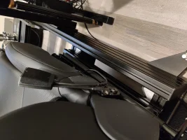

Something like that may fit there. I did better measuring to see how much room there would be comparative to this picture based on the offset of the seat in the width and it should be very similar. There will probably be a little bit less room than there is now on the right side, but I think enough to still do something like that.
I had a thought about wiring in the speed controller I was unsure of since they seem to be meant for two wire fans. Normally, voltage would be lowered if the knob is set lower than the 12 volts on the power wire. In my case, I don't need to adjust voltage on that wire to change the speed. I do it on a different wire, but if I put both those wires together since they both need access to the power, at that point I would be adjusting the voltage on the main power wire also. Logically, it doesn't necessarily sound like it should be an issue, but I don't know. I can test it by supplying 5 volts to both, but I wasn't sure if that might cause an issue if it wasn't meant to work like that.
I had a thought about wiring in the speed controller I was unsure of since they seem to be meant for two wire fans. Normally, voltage would be lowered if the knob is set lower than the 12 volts on the power wire. In my case, I don't need to adjust voltage on that wire to change the speed. I do it on a different wire, but if I put both those wires together since they both need access to the power, at that point I would be adjusting the voltage on the main power wire also. Logically, it doesn't necessarily sound like it should be an issue, but I don't know. I can test it by supplying 5 volts to both, but I wasn't sure if that might cause an issue if it wasn't meant to work like that.
boosted1g
Sustaining Member
The controller is just a set of resistors.
Power goes into the controller on red wire, as you turn the dial lower it adds more resistance and thus lowers the voltage going out the blue wire.
On a 2 wire fan you would have psu -> controler in (red wire) -> controller out (blue wire) -> fan motor in.
In your case you are connecting the PSU to both the fan (pin 4) and controller, and then controller to the speed control wire (pin 3).
You are always supplying 12V to Pin 4 of the fan, the controller only reduces voltage on the output wire (the blue wire going to pin3 of fan)..
What I am betting is that the fan is a 24V fan. Thus you are supplying const 12V on pin 4 plus the speed controlled voltage on pin 3 (thus giving it a total of 24 volts on max high, down to 14-15V on low).
Okay, so it sounds like you're saying what I was starting to think, that I would connect the PSU directly to the fan (pin 4) for full 12V power, ground through the controller connecting fan/PSU, then PSU to power wire of controller, then out to the fan at the speed control wire (pin 3), adjusting the voltage down as I see fit to change speed.
Although, you mention what I had then said I read something different on Amazon in that Motor- from controller would go into ground of fan. You mention that the voltage is lowered coming out of the blue, but doesn't that go to ground of the fan? Voltage would be lowered coming out of the red wire that goes into speed control pin, right? I know this particular controller is different from most I saw that didn't combine the + wires, so they had both +/- for both the fan side and PSU side. I was planning to getting different controller than the one you posted since it didn't have any mounting holes.
Although, you mention what I had then said I read something different on Amazon in that Motor- from controller would go into ground of fan. You mention that the voltage is lowered coming out of the blue, but doesn't that go to ground of the fan? Voltage would be lowered coming out of the red wire that goes into speed control pin, right? I know this particular controller is different from most I saw that didn't combine the + wires, so they had both +/- for both the fan side and PSU side. I was planning to getting different controller than the one you posted since it didn't have any mounting holes.
From interior to exterior to high performance - everything you need for your Stinger awaits you...