boosted1g
Sustaining Member
Be warned, this procedure is not for the faint of heart!
I apologize for not taking more pictures, I started this project not initially planning on writing a big how-to guide.
BACK STORY:
As many of you know the USB port in the center console that connects to the Radio is constant on, not switched off with the ignition.
I use a wireless android auto adapter which means it is always on with the car, which unfortunately means said adapter will randomly connect to my phone while I am home and thus kick me off my home wifi network.
So I needed this to be ignition switched to avoid having to unplug the adapter every time I come home (which completely defeats the convenience of wireless android auto/carplay)
HOW I DID IT:
First and foremost you need to get the entire module containing the USB port, aux port, cig lighter and wireless charger out of the car
You can follow this existing guide: how-to-install-oem-wireless-charger-on-your-stinger
Besides the tools in the guide above you will also need:
Tools - soldering iron, solder, precision screwdrivers, wire snips, and ideally some small needle nose pliers.
Other materials - wire, and a 12v relay (spst or spdt).
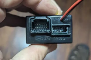
Once you have followed the guide above and have the whole thing out of the car, unplug the aux/light plug and the usb port plug from the back.
Take a flat screwdriver or other tool to push in the tabs on the side of the usb/aux module and slide it out.
Now use a small screw driver and slide it under the tabs on the sides in order to remove the front cover and then extract the circuit board.
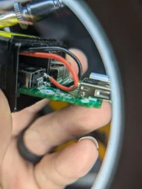
With it taken apart go ahead and drill a small hole above the raido side of the "usb" port. Here is a pic (pic shows board inside, obviously dont drill while the board is inside).

To make this work we have to cut the power pin so we can connect each side to a spst/spdt relay
Take a pair of wire snips and cut the usb power pin on the radio side USB plug. The radio side will have 4 pins at 90 degrees, while the phone side will have the pins hidden soldered to the bottom of the board.
The usb power pin is the 4th to the right pin, so the one in the middle of the board and not the right)
Now that it is cut, take a small pliers or precision screwdriver to bend the top piece of the pin to make it straight.
Now take a soldering iron and remove the bottom part of the pin you cut, and solder a new contact on the pad to connect your wire to.
Now solder one wire to the pad/solder contact you just made. Then solder another wire to the top part you bent straight.
Take care to make sure the wire does not short out to the data pins or the port casing. To make certain, I used multimeter to test continuity between each of my wires and the 3rd data pin (pin closest to the one we cut), as well continuity test between each wire and the metal casing that surrounds the port.
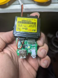
At this point it should look like this:


Now carefully slide the board and wire back into the casing, put the cover back on, slide it back into your wireless charging module and connect the USB wire to the back of the module.
Now start putting the center console back together going in reverse of how you took it apart. Once you start getting things into place, go ahead and route your wires from the USB board to wherever you plan on mounting your relay.
You will put everything together except the large top piece of the center console (the piece with cup holders, parking sensor switch, etc).
If you dont have GT2 with shift-by-wire then go ahead and leave the shift knob/boot off as well
Now wire one wire (the red one in my picture) to pin 87 of your relay, and the other (the black one in my picture) to pin 30.
Then connect the coil pins of your relay to ground and an ignition switched power source. I used the power (orange) and ground (black) wires on the rear usb port wire connector you disconnected in the other guide.
You can now start your car and verify it works as desired.
If all is well then go ahead and put back on the top cover (and shifter if not GT2).
I apologize for not taking more pictures, I started this project not initially planning on writing a big how-to guide.
BACK STORY:
As many of you know the USB port in the center console that connects to the Radio is constant on, not switched off with the ignition.
I use a wireless android auto adapter which means it is always on with the car, which unfortunately means said adapter will randomly connect to my phone while I am home and thus kick me off my home wifi network.
So I needed this to be ignition switched to avoid having to unplug the adapter every time I come home (which completely defeats the convenience of wireless android auto/carplay)
HOW I DID IT:
First and foremost you need to get the entire module containing the USB port, aux port, cig lighter and wireless charger out of the car
You can follow this existing guide: how-to-install-oem-wireless-charger-on-your-stinger
Besides the tools in the guide above you will also need:
Tools - soldering iron, solder, precision screwdrivers, wire snips, and ideally some small needle nose pliers.
Other materials - wire, and a 12v relay (spst or spdt).
Once you have followed the guide above and have the whole thing out of the car, unplug the aux/light plug and the usb port plug from the back.
Take a flat screwdriver or other tool to push in the tabs on the side of the usb/aux module and slide it out.
Now use a small screw driver and slide it under the tabs on the sides in order to remove the front cover and then extract the circuit board.
With it taken apart go ahead and drill a small hole above the raido side of the "usb" port. Here is a pic (pic shows board inside, obviously dont drill while the board is inside).

To make this work we have to cut the power pin so we can connect each side to a spst/spdt relay
Take a pair of wire snips and cut the usb power pin on the radio side USB plug. The radio side will have 4 pins at 90 degrees, while the phone side will have the pins hidden soldered to the bottom of the board.
The usb power pin is the 4th to the right pin, so the one in the middle of the board and not the right)
Now that it is cut, take a small pliers or precision screwdriver to bend the top piece of the pin to make it straight.
Now take a soldering iron and remove the bottom part of the pin you cut, and solder a new contact on the pad to connect your wire to.
Now solder one wire to the pad/solder contact you just made. Then solder another wire to the top part you bent straight.
Take care to make sure the wire does not short out to the data pins or the port casing. To make certain, I used multimeter to test continuity between each of my wires and the 3rd data pin (pin closest to the one we cut), as well continuity test between each wire and the metal casing that surrounds the port.
At this point it should look like this:


Now carefully slide the board and wire back into the casing, put the cover back on, slide it back into your wireless charging module and connect the USB wire to the back of the module.
Now start putting the center console back together going in reverse of how you took it apart. Once you start getting things into place, go ahead and route your wires from the USB board to wherever you plan on mounting your relay.
You will put everything together except the large top piece of the center console (the piece with cup holders, parking sensor switch, etc).
If you dont have GT2 with shift-by-wire then go ahead and leave the shift knob/boot off as well
Now wire one wire (the red one in my picture) to pin 87 of your relay, and the other (the black one in my picture) to pin 30.
Then connect the coil pins of your relay to ground and an ignition switched power source. I used the power (orange) and ground (black) wires on the rear usb port wire connector you disconnected in the other guide.
You can now start your car and verify it works as desired.
If all is well then go ahead and put back on the top cover (and shifter if not GT2).
Last edited:


