I was a MECP Master Certified Car Audio Installer for Circuit City and Best Buy/Geek Squad in a past life. I picked up my Stinger a few weeks ago and it made me cringe to see people grabbing power for dash cams from their OBDII ports and other random places. Grabbing power from the OBDII is an issue, because not only is it current limited, there's also issues with resolution. For example, if you are powering a dash cam but also logging, there will likely be a delay in data flow making fine tuning and troubleshooting more time
consuming and cumbersome than it otherwise should be. Not to mention you have a dongle running out of the OBDII of you car, which is just not cool.
So I figured while I was installing my dash cam and radar detector today, I would grab some pics of the proper locations to grab 12v constant, switched accessory, ignition, and a proper ground.
These wire colors are the same for the 2.0 and the 3.3, at least in the US market. Not sure about abroad, so you folks should meter these wires first. Granted, if you are connecting any component that receives a signal (i.e., dash cam or radar detector), the worst than can happen is that it will not power on or you power to say the starter wire and your device only powers on when the car is starting or you connect to the wipers and your device only powers on when the wipers are off.
The driver side knee panel is held in place by 2 Phillips head screws and a side panel secured by clips. Remove the fuse panel cover, and while using your hand push against the side panel and use a nylon panel tool to release the clips. Then use a shallow screwdriver to remove the 1 screw. Use a pik tool to release the cover to reveal the screw to the bottom right. Gently, but firmly pull the panel to remove the entire kneel panel. Be sure not to pull too hard as the OBDII wiring will still be connected.
Once you do so, you'll be greeted with this beautiful face:

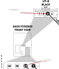
The thicker gauge white wire being held by my pik (pin 3 in the black 4 pin connector) is 12v constant (i.e., battery).

Next up is accessory. Switched accessory provides 12v whenever the car is in accessory mode or running. This is the wire that most components (i.e., dash cam and radar detectors) are connected as opposed to the OBDII port and lighting circuits. There will be some felt tape covering the connector but it is easily removed with a pik.
In the red 58 pin connector, pin 21 (thin gauge white wire) is the 12v switched accessory wire.

And just because I was down there, here is the ignition wire. This wire goes to 12v when the ignition is in the run position. In the red 58 pin connector, pin 1 (thin gauge red wire)

You can feel free to use in-line fuses with any of the above wires, it's a good practice to do so in case of a voltage spike for whatever reason, your accessories won't get fried, but if that happens the accessories are the least of your concerns.
A decent ground would be the 12mm bolt next to the fuse box located here.

Wire everything in and tape everything back up.

Put your knee bolster back into place in reverse order, don't forget about the screws.

Check out your work, you're done! Congrats!


consuming and cumbersome than it otherwise should be. Not to mention you have a dongle running out of the OBDII of you car, which is just not cool.
So I figured while I was installing my dash cam and radar detector today, I would grab some pics of the proper locations to grab 12v constant, switched accessory, ignition, and a proper ground.
These wire colors are the same for the 2.0 and the 3.3, at least in the US market. Not sure about abroad, so you folks should meter these wires first. Granted, if you are connecting any component that receives a signal (i.e., dash cam or radar detector), the worst than can happen is that it will not power on or you power to say the starter wire and your device only powers on when the car is starting or you connect to the wipers and your device only powers on when the wipers are off.
The driver side knee panel is held in place by 2 Phillips head screws and a side panel secured by clips. Remove the fuse panel cover, and while using your hand push against the side panel and use a nylon panel tool to release the clips. Then use a shallow screwdriver to remove the 1 screw. Use a pik tool to release the cover to reveal the screw to the bottom right. Gently, but firmly pull the panel to remove the entire kneel panel. Be sure not to pull too hard as the OBDII wiring will still be connected.
Once you do so, you'll be greeted with this beautiful face:

The thicker gauge white wire being held by my pik (pin 3 in the black 4 pin connector) is 12v constant (i.e., battery).

Next up is accessory. Switched accessory provides 12v whenever the car is in accessory mode or running. This is the wire that most components (i.e., dash cam and radar detectors) are connected as opposed to the OBDII port and lighting circuits. There will be some felt tape covering the connector but it is easily removed with a pik.
In the red 58 pin connector, pin 21 (thin gauge white wire) is the 12v switched accessory wire.

And just because I was down there, here is the ignition wire. This wire goes to 12v when the ignition is in the run position. In the red 58 pin connector, pin 1 (thin gauge red wire)

You can feel free to use in-line fuses with any of the above wires, it's a good practice to do so in case of a voltage spike for whatever reason, your accessories won't get fried, but if that happens the accessories are the least of your concerns.
A decent ground would be the 12mm bolt next to the fuse box located here.

Wire everything in and tape everything back up.

Put your knee bolster back into place in reverse order, don't forget about the screws.

Check out your work, you're done! Congrats!


Last edited:


