-

-
Prefer a New Age Social Media layout? CLICK HERE! (This message can be dismissed by clicking the X in the right corner)
Social Feed
What's on your mind?
The window on the driver side started doing this almost one year ago, so I went to the dealer and they replaced the whole window lift assembly except the motor. The problem was still there, so they replaced the rubber channel, which still didn't fix the issue. They are now thinking to replace the motor...
A couple of weeks ago the same problem started on the passenger side and today all windows present the same issue.
The problem is not related to the window button/command, it happens also when using the key fob.
Is this happening to anyone else? Any idea what the problem is and how to fix it?
Thanks!
0 replies
·
10 views
replies
Legacy View
Hi everyone,
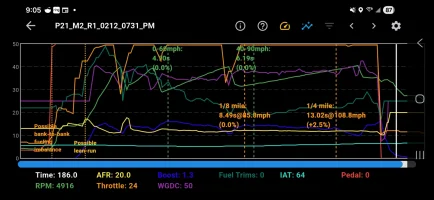
I recently got a 19' GT1 AWD, and I have the BMS 450WHP kit, and a TiAL BOV, with the BMS adapter and I was wondering if this looks good for a 1/4-mile run. I have been reading into the expected boost levels and was wondering if these logs look alright or not. Any help is greatly appreciated.
I recently got a 19' GT1 AWD, and I have the BMS 450WHP kit, and a TiAL BOV, with the BMS adapter and I was wondering if this looks good for a 1/4-mile run. I have been reading into the expected boost levels and was wondering if these logs look alright or not. Any help is greatly appreciated.
8 replies
·
118 views
With the Stinger's release right around the corner, Post pics and give updates of what you did to your Stinger. From a simple car wash to installing aftermarket items. Andddddd go!
There's lots of mods and upgrades to be seen at KDM Warehouse!

 kdmwarehouse.com
There's lots of mods and upgrades to be seen at KDM Warehouse!
Kia Stinger
K Stinger badges, emblems and lots of other items. High performance and cosmetic modifications made specifically for your Kia Stinger.
kdmwarehouse.com
15160 replies
·
2415035 views

So the other day I was driving home from work and the battery charging system dash light would flash on for a quick half second a couple times but not a steady flash it was at random intervals. I had a new battery installed last year, the alternator is putting out 14 volts and when the engine isn't running im getting 12.7 volts. Ran the battery through a tester and tested good. Just wondering if anyone else has had this problem before I really start digging into it as it does it very randomly still. Thanks for the help guys!
0 replies
·
13 views
replies
Legacy View
Hey Max here. Just signed up for the forum . I made a mistake and bought the wrong size rim for my 2020 Stinger it’s 19” OEM if anyone’s interested in needed a spare rim feel free to send offers .
Just trying to get rid of it since I ordered the correct part and can’t send the old one back.
I will provide all the paperwork/ pictures you need to inspect the Wheel .
Thanks and looking forward to making more posts about my upgrades & Mods.
Just trying to get rid of it since I ordered the correct part and can’t send the old one back.
I will provide all the paperwork/ pictures you need to inspect the Wheel .
Thanks and looking forward to making more posts about my upgrades & Mods.
6 replies
·
75 views

Is very proud to present to the Stinger forums:
3.0 K Emblem Sets "Black Edition"
(BUY NOW)
Description:
These 3.0 K "Black Edition" emblems are a perfect upgrade/replacement for your boring KIA emblems
These are the authentic 3.0 K "Black Edition" Emblems manufactured in South Korea
Available in Black, Black Carbon Fiber, White Carbon Fiber, Blue & Red
All orders ship same day if placed before 4pm PST/7pm EST
Emblem Sets:
7pc Set = Front/Rear/Steering Wheel/Wheels Caps
3pc Set = Front/Rear/Steering Wheel
2pc Set = Front/Rear
Vehicle Applications:
2018-2023 Kia Stinger (All models)
(All KIA Models)
Installation Guide:
Installation Instructions: (FOUND HERE)


THANK YOU FOR LOOKING!
17 replies
·
14302 views
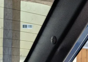
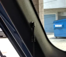
This part broke off this weekend, anyone have any idea how to dig up the P/N for a replacement?


16 replies
·
7050 views
TLDR: If I went to 245/35r18 (or 255) tires all around for track days, what effect would that have on handling?
I had a very fun and rewarding track day with all my track focused improvements done (new PB's are always exciting), one of which was the Cup2 tires (235/40r19 front and 265/35r19 rear).
I tracked the wear and tear and found that the fronts wore 1.27mm left & 1.15mm right, while the rears didn't wear at all.
I get the feeling the front OEM tires are undersized for hard braking and cornering, so if I widen those, I might as well meet in the middle with the rears for a square setup. At this rate the rears will probably age out before they wear out, but going to a square 245 or 255 setup would let me rotate the tire's any which way and even out the tread wear.
Was also considering dropping to 18" rims to reduce unsprung mass. Any input would help before I go finding out the hard way .
.
I had a very fun and rewarding track day with all my track focused improvements done (new PB's are always exciting), one of which was the Cup2 tires (235/40r19 front and 265/35r19 rear).
I tracked the wear and tear and found that the fronts wore 1.27mm left & 1.15mm right, while the rears didn't wear at all.
I get the feeling the front OEM tires are undersized for hard braking and cornering, so if I widen those, I might as well meet in the middle with the rears for a square setup. At this rate the rears will probably age out before they wear out, but going to a square 245 or 255 setup would let me rotate the tire's any which way and even out the tread wear.
Was also considering dropping to 18" rims to reduce unsprung mass. Any input would help before I go finding out the hard way
.
32 replies
·
2797 views
3.3TT Low Oil Pressure
Seeing if anyone has had any experience with this before I take it to the dealer.
Oil pressure light comes on while idling, under 800 RPM it will come on and go off once I go over 800 RPM.
No CEL, oil is at Full mark on stick, oil changed 2k miles ago with 5w-30, at 61k miles.
Oil pressure light comes on while idling, under 800 RPM it will come on and go off once I go over 800 RPM.
No CEL, oil is at Full mark on stick, oil changed 2k miles ago with 5w-30, at 61k miles.
141 replies
·
40861 views
I dug up a bunch of old photos and files related to this project from August 2024 that I want to share with whomever is interested in this type of thing. This project is not over and I am still developing this, now with a much better design and combination with my own 'brake snip' modification, so stay tuned for that I guess.
///
I've owned a wind booster GT (GT607L) for a long time and am quite fond of this little gadget. I had it on my '18 GT limited and now on my '23 GT limited. This post is about the customization I have done to my unit and the ongoing development of a higher quality, permanent design to share with the community.
It began when I had the module installed on my '18 Stinger and experienced a few dangerous situations where the device malfunctioned and randomly caused unintended acceleration rise while driving and even limp mode due either a module fault, faulty electrical connection or a significant mismatch between throttle position and feedback signal. I don't know.
I thought my wind booster may have been permanently faulty and removed it from the car. I decided to hang onto it and develop a full bypass back-to-stock relay module to activate as soon as I detect a malfunction. The details of this relay module are what I will share here.


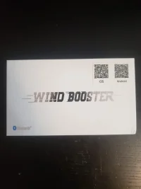
The GT607L.
Back-to-stock bypass means full electrical isolation of the wind booster module from the electrical connector of the accelerator pedal and the electrical connector of the car-side wiring. The standard installation requires the wind booster module be inserted "in-line" between the car-side connector and the accelerator pedal. There are (2) 6-pin connectors passing (6) wires in and (6) wires out (12 total) of the wind booster module. To completely isolate the module from the car-side and accelerator side, an additional 12 wires are needed for a total of 24. This is accomplished by implementing (3) 4PDT (four-pole-double-throw) control relays to handle the switching of 24 connections.
If you happen to have a strong understanding of electromechanical relays, you can skip this next part where I explain the function and operation.
4PDT means four isolated connections (four-pole) "IN" with two (double throw) "OUT" paths each, where each (double throw) has both a normally open (N.O.) and normally closed (N.C.) contact (pathway) to make external connections with. This configuration is known as a "form C" contact arrangement.
Three (3) 4PDT represents (12) "IN" paths and (24) "OUT" paths across all relays. "Normal" is the term used to describe the state of a relays electrical contacts (pathways) when no electrical activation signal is applied to the electromagnetic coil - it can also be referred to being at, "rest". The "not-normal" state describes the other condition, where an electrical activation signal is applied to the electromagnetic coil and the electrical contacts (pathways) physically change internally (changeover) due to armature (linkage) movement. It's important to mention that a form C contact arrangement is non-polarized, meaning the "IN" and "OUT" sides that I described are not functionally significant but rather, intuitively helpful.
To summarize the double throw relay function:
- A N.C. (normally closed) pathway will have electrical continuity from "IN" to "OUT" on the "OUT" (throw) indicated as N.C.
- A N.O. (normally open) pathway will not have electrical continuity from "IN" to "OUT" on the "OUT" (throw) indicated as N.O.
- These electrical states are always inverse of each other
Across four (4) 4PDT relays there are (12) N.C. contacts available. I used these contacts to bypass the wind booster module. In this way the male electrical connector from the car can be connected directly to the female electrical connector on the accelerator pedal. Conversely, (12) N.O. contacts are available and used to connect the same male and female 6-pin electrical connectors (car-side and accelerator pedal) instead to the 6 input and output wires, respectively, of the wind booster module.
Interposing wiring and neat extension splicing is required to make these connections remotely as described.

Four (4) 6/C (6-conductor) cables are needed to make 24 connections to the three (3) 4PDT relays. I used #18 AWG.


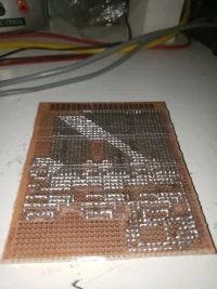
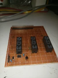
I made this proto-board circuit in August 2024. Here you can see the through-hole relays which are Omron KS23051: DC 5V 4P2T 2A. This circuit is powered by 5 VDC sourced from the USB port in the car. To make this work, the relay coils had to be connected in parallel.

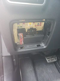
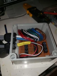
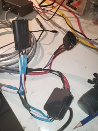
Here is the circuit board in a weatherproof enclosure with the cabling brought in with glands. This enclosure is fastened to the left of the steering column, near the wiring penetration to the engine compartment. There is enough space to tuck it away and when secured high and tight it will never touch one's feet and interfere with driving in any way.

I dug up the old layout for proto-board assembly.

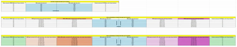
Here is the wiring map that I came up with to identify all connections. This is to be interpreted with a left-to-right flow.

Here is the completed assembly, ready for installation.

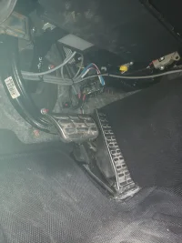
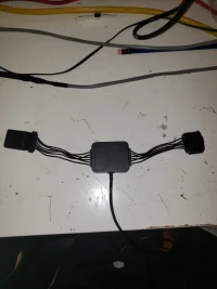
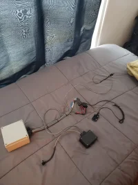
Here is the wind booster module tucked away with all the splices, the car connection to the module harness is zip tied on top. You can also see the entire cable bundle zip tied loosely to the steering column. This has caused no issues whatsoever in terms of steering impairment, or cable wear. It was pretty much the only option to secure the cabling this high up which is the goal. This has been installed like this since August 2024 and has survived two winters.

This is the control location for activation using one of these illuminated switches. The other one was for something unrelated.
///
I've owned a wind booster GT (GT607L) for a long time and am quite fond of this little gadget. I had it on my '18 GT limited and now on my '23 GT limited. This post is about the customization I have done to my unit and the ongoing development of a higher quality, permanent design to share with the community.
It began when I had the module installed on my '18 Stinger and experienced a few dangerous situations where the device malfunctioned and randomly caused unintended acceleration rise while driving and even limp mode due either a module fault, faulty electrical connection or a significant mismatch between throttle position and feedback signal. I don't know.
I thought my wind booster may have been permanently faulty and removed it from the car. I decided to hang onto it and develop a full bypass back-to-stock relay module to activate as soon as I detect a malfunction. The details of this relay module are what I will share here.
The GT607L.
Back-to-stock bypass means full electrical isolation of the wind booster module from the electrical connector of the accelerator pedal and the electrical connector of the car-side wiring. The standard installation requires the wind booster module be inserted "in-line" between the car-side connector and the accelerator pedal. There are (2) 6-pin connectors passing (6) wires in and (6) wires out (12 total) of the wind booster module. To completely isolate the module from the car-side and accelerator side, an additional 12 wires are needed for a total of 24. This is accomplished by implementing (3) 4PDT (four-pole-double-throw) control relays to handle the switching of 24 connections.
If you happen to have a strong understanding of electromechanical relays, you can skip this next part where I explain the function and operation.
4PDT means four isolated connections (four-pole) "IN" with two (double throw) "OUT" paths each, where each (double throw) has both a normally open (N.O.) and normally closed (N.C.) contact (pathway) to make external connections with. This configuration is known as a "form C" contact arrangement.
Three (3) 4PDT represents (12) "IN" paths and (24) "OUT" paths across all relays. "Normal" is the term used to describe the state of a relays electrical contacts (pathways) when no electrical activation signal is applied to the electromagnetic coil - it can also be referred to being at, "rest". The "not-normal" state describes the other condition, where an electrical activation signal is applied to the electromagnetic coil and the electrical contacts (pathways) physically change internally (changeover) due to armature (linkage) movement. It's important to mention that a form C contact arrangement is non-polarized, meaning the "IN" and "OUT" sides that I described are not functionally significant but rather, intuitively helpful.
To summarize the double throw relay function:
- A N.C. (normally closed) pathway will have electrical continuity from "IN" to "OUT" on the "OUT" (throw) indicated as N.C.
- A N.O. (normally open) pathway will not have electrical continuity from "IN" to "OUT" on the "OUT" (throw) indicated as N.O.
- These electrical states are always inverse of each other
Across four (4) 4PDT relays there are (12) N.C. contacts available. I used these contacts to bypass the wind booster module. In this way the male electrical connector from the car can be connected directly to the female electrical connector on the accelerator pedal. Conversely, (12) N.O. contacts are available and used to connect the same male and female 6-pin electrical connectors (car-side and accelerator pedal) instead to the 6 input and output wires, respectively, of the wind booster module.
Interposing wiring and neat extension splicing is required to make these connections remotely as described.
Four (4) 6/C (6-conductor) cables are needed to make 24 connections to the three (3) 4PDT relays. I used #18 AWG.
I made this proto-board circuit in August 2024. Here you can see the through-hole relays which are Omron KS23051: DC 5V 4P2T 2A. This circuit is powered by 5 VDC sourced from the USB port in the car. To make this work, the relay coils had to be connected in parallel.
Here is the circuit board in a weatherproof enclosure with the cabling brought in with glands. This enclosure is fastened to the left of the steering column, near the wiring penetration to the engine compartment. There is enough space to tuck it away and when secured high and tight it will never touch one's feet and interfere with driving in any way.
I dug up the old layout for proto-board assembly.
Here is the wiring map that I came up with to identify all connections. This is to be interpreted with a left-to-right flow.
Here is the completed assembly, ready for installation.
Here is the wind booster module tucked away with all the splices, the car connection to the module harness is zip tied on top. You can also see the entire cable bundle zip tied loosely to the steering column. This has caused no issues whatsoever in terms of steering impairment, or cable wear. It was pretty much the only option to secure the cabling this high up which is the goal. This has been installed like this since August 2024 and has survived two winters.
This is the control location for activation using one of these illuminated switches. The other one was for something unrelated.

0 replies
·
39 views
replies
Legacy View
I have had the Mando unit installed early on from when they became available and found it really makes a difference.. Recently it has stopped working in that I can't activate the Module Status Setting.
The App is working okay and the mando unit connects. I can change the automatic connection no problem but the Module Status Setting refuses to activate. The error message "It is not possible to inquire vehicle information" comes up. Settings can be changed on the app but then an error comes up saying the Apply Failed. I have uninstalled the app on my phone and reinstalled and have tried on another phone but no luck. I have also disconnected the mando unit from power to see if it resets but no luck.
Has anyone had the problem and found a solution?
17 replies
·
3134 views