Social Feed
What's on your mind?
With the Stinger's release right around the corner, Post pics and give updates of what you did to your Stinger. From a simple car wash to installing aftermarket items. Andddddd go!
There's lots of mods and upgrades to be seen at KDM Warehouse!

 kdmwarehouse.com
There's lots of mods and upgrades to be seen at KDM Warehouse!
Kia Stinger
K Stinger badges, emblems and lots of other items. High performance and cosmetic modifications made specifically for your Kia Stinger.
kdmwarehouse.com
15222 replies
·
2480422 views

Hello all. Been a while since I have been back here. Still loving my Stinger but have a recent issue at 74k miles. Had a nice "chat" with ChatGPT after talking to my service rep. They are still diagnosing the issue but figured I would document the issue here in case it helps anyone else in the future. I was able to upload the Kia Warranty and my Extended Warranty for additional context. I asked ChatGPT to summarize our conversation just so I had all the information organized.
Car:
2019 Kia Stinger GT (3.3TT)
~74,000 miles
Initial Symptoms:
Escalation:
Dealer Actions So Far:
What This Likely Points To (based on research + feedback):
Warranty Situation:
Important Notes for Others:
Current Status:
Waiting on final diagnosis from dealer + Kia corporate
Will update once I know whether it’s a repair or full engine replacement
Hope this helps someone else—happy to answer questions or update once resolved. Some of this info is probably obvious to alot of you on here but I am not super educated on cars but love my Stinger!
Car:
2019 Kia Stinger GT (3.3TT)
~74,000 miles
Initial Symptoms:
- Check engine light with misfires on cylinders 1, 3, and 5 (same bank)
- Car would go into limp mode
- Issue would temporarily reset after restarting the engine
Escalation:
- Problem became more frequent
- Eventually the check engine light stayed on
- Car stalled at a stoplight (restarted after putting it in park)
- Dropped the car off at the dealer immediately
Dealer Actions So Far:
- Replaced spark plugs and ignition coils → did NOT fix issue
- Now diagnosing further with Kia tech support
- Mentioned finding oil pooling
- Indicated that engine replacement is a possibility (still under investigation)
What This Likely Points To (based on research + feedback):
- Not ignition-related (already ruled out)
- Likely a bank-specific issue (since 1,3,5 all affected)
- Most probable causes:
- Fuel system issue (injectors / fuel delivery)
- Turbo oil seal / oil ingestion
- PCV system issue
- VVT / cam timing issue
- Internal engine issue (rings/valves)
Warranty Situation:
- Basic warranty expired (5yr / 60k)
- Powertrain warranty (10yr / 100k) still active
- Issue clearly falls under:
- Engine internals
- Fuel system
- Turbo system
Important Notes for Others:
- If you get multiple misfires on one bank, don’t assume it’s just plugs/coils
- Limp mode + stalling = serious underlying issue
- Bring the car in ASAP and avoid driving it
- Let the dealer diagnose BEFORE paying for repairs yourself
- Even without perfect maintenance records, warranty claims can still be valid unless neglect directly caused the issue
Current Status:
Waiting on final diagnosis from dealer + Kia corporate
Will update once I know whether it’s a repair or full engine replacement
Hope this helps someone else—happy to answer questions or update once resolved. Some of this info is probably obvious to alot of you on here but I am not super educated on cars but love my Stinger!
18 replies
·
325 views

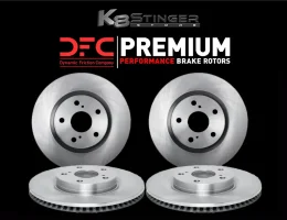
Is excited to present to the Stinger forums:
DFC Brake Rotors
(BUY NOW)
Description:
Give your Kia Stinger the reliable stopping power it deserves with DFC GeoSpec® coated rotors
Built for durability, corrosion resistance, and smooth performance, these DFC GeoSpec® rotors deliver OEM+ levels of braking
provides superior protection against rust and corrosion on non-friction surfaces
Premium iron castings deliver durability, strength, and long service life
Designed as a replacement for factory Kia Stinger brake rotors
Precision-cut and balanced for smoother stops and less vibration
Non-directional finish for quicker break-in and consistent braking
OE vane configuration ensures proper heat dissipation
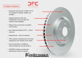
Features:
Choose front (2), rear (2), or full set (4) rotors
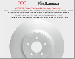
GeoSpec® corrosion-resistant coating
Direct replacement of your factory rotors
Non-directional brake surface for quiet operation
Vented rotor design for effective heat management
These pair great with our K8SS Elite Sport Ceramic Brake Pads on the website:
Vehicle Application:
2018–2023 Kia Stinger (3.3T Models Only)


THANK YOU FOR LOOKING!

0 replies
·
6 views
replies
Legacy View
Is proud to present to the Stinger forums:
E Logo Steering Wheel Emblem
(BUY NOW)
Description:
Replace your boring "KIA" steering wheel emblem with this stylish OEM style E logo emblem
This added attention to detail matches that of the OEM front E logo emblem and OEM E logo wheels caps
Trademarked OEM-style patterned glossy black background with chrome E logo and surround
Produced with OEM quality fit and finish
Vehicle Application:
2018-2021 Kia Stinger (All Models)
THANK YOU FOR LOOKING!
2 replies
·
5529 views
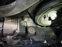
Anyone else have oil leaking from this location?
Went to do an oil change today, and notice oil dripping on the steering rack motor. seems to be either coming out of the top of the oil filter housing near the crank and or from where the oil cooler attaches to the filter housing.
Anyone else have this issue?
Car is a 2022 GT2 with 72,000 miles
pic is below
83 replies
·
13857 views
Hello Everyone, I am a long time Stinger owner, but first time poster. I was looking to gather opinions to get an idea when I should change the spark plugs on my 2021 Stinger GT. The mileage on the car is relatively low, given that I purchased the car new in 2020. It just a tick over 40k miles and mostly freeway. I use a high quality premium gas and the car runs great.
Back in the day, I would do all the maintenance work on my cars myself, but I can no longer do for many reasons. The dealership wants $700 to do it as a “recommended” service interval. I’m calling BS, but wanted to get other opinions. Thanks in advance.
Back in the day, I would do all the maintenance work on my cars myself, but I can no longer do for many reasons. The dealership wants $700 to do it as a “recommended” service interval. I’m calling BS, but wanted to get other opinions. Thanks in advance.
19 replies
·
248 views
Thanks for the add! I'm looking to buy a Stinger and here to learn about them.
29 replies
·
497 views
Is here to present another great product:
HKS M45iL Spark Plugs
(BUY NOW)
Description:
HKS M-Series Super Fire Racing spark plugs are high performance
Iridium plugs designed to handle advanced levels of tuning and provide Improved ignition performance, durability & anti-carbon build-up
Sold as (1) plug or a (6) pack. Pick from drop down menu
Compare our pricing to others who sell these plugs.
We are happy to match the pricing of other dealers in the US
Features & Specs:
0.6mm Iridium Alloy Center Electrode: Iridium Alloy Center Electrode reduces voltage
requirement as well as improving ignition performance and durability
Outer Electrode with Platinum Chip: The Outer Electrode incorporates a square platinum
chip which improves durability, and when combined with the iridium center electrode boosts ignition performance
Short Type Outer Electrode (Anti-Vibration): The outer electrode has been shortened and engineered
with the ideal shape to decrease weight for resistance against vibration. This anti-vibration design improves longevity of the outer electrode
Thermal Edge: After long idling or various combustion conditions carbon
buildup can occur causing misfires. The Thermal Edge of the ceramic insulator will discharge to help decrease carbon deposits
Spark Support Gap: Discharges will occur in the Spark Support Gap
(Space between the tip of the insulator and the base of the outer electrode) to help prevent carbon buildup
Vehicle Applications:
Specifically sold for use with the Kia Stinger, G90, & G80 vehicles


THANK YOU FOR LOOKING!
9 replies
·
8899 views
Just a few days back, I found I cannot make phone calls in the car. So what happens is I press the call button on the steering wheel and say, "Call Julie on mobile" and the car responds "Calling Julie on mobile" What happens from this point on is that all sound stops. I cannot hear the dialed phone ringing and I can tell when it is answered as I can see the call timer start. The called party hear nothing and I hear nothing. Have tried it with the cable connection and also with bluetooth. Same reult. Tried another iPhone and same issue. Tried with two android phones and same issue. Have updated OS on the phone and also downloaded latest firmware from KIa and installed. it. Sent an enquiry to local dealer.. no reply. Sent an enquiry to Kia themselves (here in Australia) and so far no reply. So.. was wondering if anybody else on the form has had this issue. All other features work, Waze, Music etc. Just calls that are the issue. Also tried resetting head unit, disconnecting the battery for a half hour... no change. Any comments or experiences most welcome.
1 replies
·
54 views
First time posting long time learning from this thread.
I’m gonna purchase a CPI kit from BMS along with their intercooler. I had a few questions before doing so. I will obviously have the correct BEF from BMS to run higher ethanol from the cpi but my question comes down to whether I can run full e85 or not. Will the 1500cc nozzle help with being able to push a higher ethanol content through or should I just stick with the 950? I’ve seen a few people say they’ve been able to run full e85 (I’m sure this also comes from adjusting settings for watermeth/cpi in the jb4 app) . I’m not looking to get better gains from running full e85 I’ve seen many say you dont get that much more performance past e60 on this bef. Im doing it just to be able to fill up and not mix/ waste time at pump
I’m still new to tuning and upgrading so any advice would be greatly appreciated
0 replies
·
41 views
replies
Legacy View
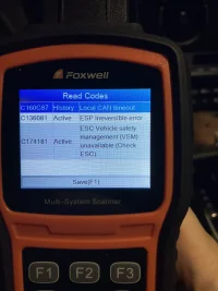
2018 GT2 AWD, 108k mi, looks like my good luck might finally be running out.
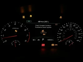
Here's what my dash looks like after driving around the block:

As you can see, I've been accumulating lights on my dash over the last ~9 months. First, the EPB, red Brake and amber Auto Hold lights would come on intermittantly, then as of about 4 months ago they came on as soon as I start the car and stay on. This would also disable cruise control whenever the lights were on.
The traction, ABS, forward collision, and the top right warning lights came next ~2 months ago, just randomly showed up one day and come on and stay on as soon as I start the car now.
The AWD light in the top left does not come on when I start the car, but comes on soon after driving for a bit.
Mechanically, the car still feels absolutely fine, except for the fact that the cruise control is disabled and the front wheels no longer get power once the ABS light comes on. The front parking sensors still work but presumably the actual forward collision avoidance is disabled as well. No weird noises, no starting problems, no actual CEL or anything like that.


Those are all the codes I currently have. Initial Googling wasn't too helpful, but some responses told me that maybe my battery could be on it's way out. I had it load tested at a local place and they said it's a touch low but still well within acceptable, and since I'm not having any other starting/electrical problems and they didn't even try to sell me a new one I figured I'm good there. The only other things Google immediately turned up were either a general wiring issue somewhere or...


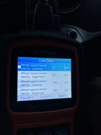
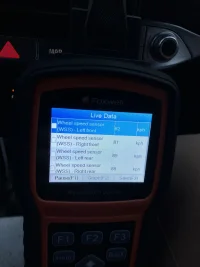
Pics from my wheel speed sensors. That seems to be the first common problem that would cause this, but I'm not really sure what's going on here. As you can see, they're reading rather different values between front and rear. First pic was taken at ~55 MPH. Immediately I thought my tires must just be uneven. So, I went home and swapped my fronts and rear wheels around (I have square 235/45R18s). Second pic is ~60 MPH after swapping my front and rear tires, same issue. First of all, if a sensor was bad, wouldn't it just be reporting nothing? Is it possible that two of the sensors are failing at the exact same time, and in exactly the same way?
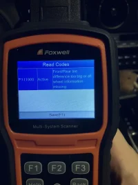
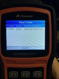
Other than that, the only thing that looks obvious to me is the C138201 Hall level sensor fault. Again, Googling didn't turn up too much on this so I'm not really sure where to go with that, and would that really be causing all these problems?
I haven't tried clearing any of the codes yet. Almost all of them are reading as active though so I assume they would just come back. Anyone have any idea how I can fix this? I would prefer to order parts and do the work myself if possible if someone can point me at what to replace. Thank you!!
Here's what my dash looks like after driving around the block:
As you can see, I've been accumulating lights on my dash over the last ~9 months. First, the EPB, red Brake and amber Auto Hold lights would come on intermittantly, then as of about 4 months ago they came on as soon as I start the car and stay on. This would also disable cruise control whenever the lights were on.
The traction, ABS, forward collision, and the top right warning lights came next ~2 months ago, just randomly showed up one day and come on and stay on as soon as I start the car now.
The AWD light in the top left does not come on when I start the car, but comes on soon after driving for a bit.
Mechanically, the car still feels absolutely fine, except for the fact that the cruise control is disabled and the front wheels no longer get power once the ABS light comes on. The front parking sensors still work but presumably the actual forward collision avoidance is disabled as well. No weird noises, no starting problems, no actual CEL or anything like that.
Those are all the codes I currently have. Initial Googling wasn't too helpful, but some responses told me that maybe my battery could be on it's way out. I had it load tested at a local place and they said it's a touch low but still well within acceptable, and since I'm not having any other starting/electrical problems and they didn't even try to sell me a new one I figured I'm good there. The only other things Google immediately turned up were either a general wiring issue somewhere or...
Pics from my wheel speed sensors. That seems to be the first common problem that would cause this, but I'm not really sure what's going on here. As you can see, they're reading rather different values between front and rear. First pic was taken at ~55 MPH. Immediately I thought my tires must just be uneven. So, I went home and swapped my fronts and rear wheels around (I have square 235/45R18s). Second pic is ~60 MPH after swapping my front and rear tires, same issue. First of all, if a sensor was bad, wouldn't it just be reporting nothing? Is it possible that two of the sensors are failing at the exact same time, and in exactly the same way?
Other than that, the only thing that looks obvious to me is the C138201 Hall level sensor fault. Again, Googling didn't turn up too much on this so I'm not really sure where to go with that, and would that really be causing all these problems?
I haven't tried clearing any of the codes yet. Almost all of them are reading as active though so I assume they would just come back. Anyone have any idea how I can fix this? I would prefer to order parts and do the work myself if possible if someone can point me at what to replace. Thank you!!
11 replies
·
699 views